This is the multi-page printable view of this section. Click here to print.
Guides
- 1: Envoy Gateway
- 1.1: Direct (PROXY-protocol) mode
- 1.2: Proxy (X-Forwarded-For) mode
- 1.3: Migrating from ingress-nginx
- 2: Cert-manager and Cloudflare demo
- 3: Change PV StorageClass
- 4: Ingress and cert-manager
- 5: Install and upgrade cert-manager
- 6: Install and upgrade ingress-nginx
- 7: Load balancers
- 8: Migration to Kubernetes CaaS v2
- 9: Node labels and taints with elx-nodegroup-controller
- 10: Persistent volumes
- 11: Your first deployment
1 - Envoy Gateway
This section introduces Envoy Gateway as the ingress controller in our
Elastx Kubernetes CaaS service. We manage and upgrade the controller, the
Gateway API CRDs and the cluster-scoped
GatewayClass named eg. You create the Gateway API
objects that describe your own traffic in your own namespaces.
There are companion guides for the two ways traffic typically reaches the cluster. Pick the one that matches your setup:
- Direct (PROXY-protocol) mode: clients connect straight to the load balancer.
- Proxy (X-Forwarded-For) mode: a customer-owned upstream proxy (CDN, WAF, edge proxy) sits in front of the load balancer.
Standard layout: one shared Gateway per cluster
A cluster has one shared Gateway in a dedicated namespace (for example
gateway) that serves routes from all your application namespaces through a
single OpenStack load balancer and IP. This is the standard setup and the
direct equivalent of ingress-nginx, where a single controller fronted every
host in the cluster. Each application namespace opts in with a
shared-gateway-access: "true" label and contributes its own HTTPRoutes,
and never touches the shared Gateway.
%%{init: {'theme':'base','themeVariables':{'primaryColor':'#DAE7EC','primaryBorderColor':'#1E343E','primaryTextColor':'#1E343E','lineColor':'#5A7A8A','clusterBkg':'#EEF3F6','clusterBorder':'#9BB3BF','edgeLabelBackground':'#FFFFFF'}}}%%
flowchart TB
client(["Clients"]):::client --> lb["OpenStack load balancer<br/>one LB · one IP"]:::lb
lb --> gw
subgraph gwns["gateway namespace"]
gw["Gateway 'shared'"]:::gw
ctp["ClientTrafficPolicy"]:::policy
cert["TLS certificates<br/>per hostname"]:::policy
end
ctp -.->|attaches to| gw
cert -.->|terminates TLS| gw
subgraph ta["team-a namespace"]
appa["app + HTTPRoute"]:::app
end
subgraph tb["team-b namespace"]
appb["app + HTTPRoute"]:::app
end
gw -->|"team-a.example.com"| appa
gw -->|"team-b.example.com"| appb
classDef client fill:#FFFFFF,stroke:#1E343E,color:#1E343E;
classDef lb fill:#DAE7EC,stroke:#1E343E,color:#1E343E;
classDef gw fill:#FBBD18,stroke:#1E343E,stroke-width:2px,color:#1E343E;
classDef policy fill:#F5F8FA,stroke:#1E343E,color:#1E343E;
classDef app fill:#DAE7EC,stroke:#1E343E,color:#1E343E;
Each Gateway provisions its own OpenStack load balancer, so a single shared
Gateway keeps your cluster on one load balancer, one IP and one
ClientTrafficPolicy: the same single-entry-point model you had with
ingress-nginx. TLS is terminated centrally in the gateway namespace, with one
certificate per hostname (Envoy serves the right one per request by SNI). The
walkthroughs below use this layout throughout. Running more than one
Gateway, a separate load balancer for a single namespace via
allowedRoutes.namespaces.from: Same, is a non-standard setup for the rare case
that genuinely needs an isolated IP or blast radius.
What you create
In the dedicated gateway namespace (once, by whoever owns ingress):
Gateway: listeners, ports, protocols, TLS;allowedRoutesselecting theshared-gateway-access: "true"label.ClientTrafficPolicy: controls PROXY-protocol handling, TLS parameters, timeouts. Must live in the same namespace as theGateway.- TLS
Certificate/Issuer(cert-manager): one certificate per hostname you serve (HTTP-01 in direct mode, DNS-01 in proxy mode). - Optionally, an HTTP-to-HTTPS redirect
HTTPRouteon thehttplistener, to match ingress-nginx’sssl-redirectbehaviour for every host.
In each application namespace (per team, self-service):
- The
shared-gateway-access: "true"namespace label. HTTPRoute,GRPCRoute: routing rules, attached to the sharedGatewayvia cross-namespaceparentRefs.BackendTrafficPolicy: retries, circuit breaking.SecurityPolicy: JWT, OIDC, CORS.BackendTLSPolicy: mTLS toward your backends.
You reference the cluster GatewayClass by its name eg from the
Gateway. You do not need to create or modify any cluster-scoped resources.
Which variant fits your setup?
The OpenStack load balancer in front of Envoy runs in TCP mode in both
cases. The variants differ in how the real client IP arrives at
Envoy, and your ClientTrafficPolicy has to match.
- Direct (PROXY-protocol) mode: clients connect straight to the
load balancer. The load balancer is configured with PROXY protocol v2
and prepends a PROXY header carrying the real client IP. Your
ClientTrafficPolicymust enable proxy-protocol parsing. See Direct (PROXY-protocol) mode. - Proxy (X-Forwarded-For) mode: you put your own upstream proxy
(CDN, WAF, edge proxy) in front of the load balancer. That upstream
injects the real client IP into
X-Forwarded-For; the load balancer passes the request through unchanged. YourClientTrafficPolicymust trust that header with the right hop count. See Proxy (X-Forwarded-For) mode.
Coming from ingress-nginx?
If you used our managed ingress-nginx, the two modes carry over directly; only the names and the resources you write have changed:
| ingress-nginx | Envoy Gateway | When it applies |
|---|---|---|
Direct mode (use-proxy-protocol: "true") |
Direct (PROXY-protocol) mode | Clients connect straight to our load balancer. No upstream proxy. This is the default. |
Proxy mode (use-forwarded-headers: "true") |
Proxy (X-Forwarded-For) mode | You run your own CDN / WAF / edge proxy in front of the load balancer. |
As before, the mode is a cluster-level setting: we provision your
cluster in one mode or the other; you do not switch it from a manifest. Tell us
which fits your setup and we configure the load balancer accordingly. What you
do write is a ClientTrafficPolicy that matches that mode (see the two
guides above).
Proxy mode requires your own upstream proxy. X-Forwarded-For mode only makes sense when a CDN, WAF, or edge proxy actually sits in front of the load balancer and injects the header. Without one, no real client IP ever reaches Envoy and your backends see only the load balancer. If clients connect directly to Elastx, use direct (PROXY-protocol) mode instead. It carries the client IP for you and needs no CDN.
Two things also changed with Kubernetes CaaS v2:
- Ingress always enters through the load balancer. Older clusters accepted
traffic directly on each worker node’s floating IP; that path is gone. DNS for
your services now points at the
Gateway’s load-balancer address. - Floating IPs are an opt-in egress feature, used for a predictable outbound source IP, not as an ingress path.
For the full move, including clusters that use floating IPs, see Migrating from ingress-nginx.
TLS
Both walkthroughs terminate TLS on the shared Gateway, with cert-manager
issuing one certificate per hostname into the gateway namespace (the same
namespace as the Gateway). The validation method differs by mode: direct mode
uses ACME HTTP-01 (clients reach the load balancer directly), while proxy mode
uses DNS-01 (public DNS points at your upstream proxy, so HTTP-01 cannot reach
Envoy). If you need a guide for installing cert-manager, see
Install and upgrade cert-manager.
Advanced usage
For more advanced use cases please refer to the documentation provided by each project or contact our support:
1.1 - Direct (PROXY-protocol) mode
This guide walks through setting up Envoy Gateway in a cluster where the
OpenStack load balancer is configured in TCP mode with PROXY protocol v2.
The load balancer prepends a PROXY header to each incoming connection
carrying the real client IP. Envoy parses that header and uses it for
access logs, rate limiting and X-Forwarded-For.
Note: Your
ClientTrafficPolicymust setproxyProtocol.optional: false. Without it Envoy parses the load balancer’s PROXY-v2 prefix as a malformed HTTP request and every response isHTTP 400 Bad Request.
If you are not sure which variant applies to your cluster, see the Envoy Gateway overview.
The shared-Gateway layout
A cluster runs one shared Gateway in a dedicated namespace that serves
routes from all your application namespaces through a single load balancer
and IP. Each application namespace opts in with a label and contributes its own
HTTPRoutes. This is the standard setup, the same single-entry-point model
ingress-nginx gave you, where one controller fronted every host.
%%{init: {'theme':'base','themeVariables':{'primaryColor':'#DAE7EC','primaryBorderColor':'#1E343E','primaryTextColor':'#1E343E','lineColor':'#5A7A8A','clusterBkg':'#EEF3F6','clusterBorder':'#9BB3BF','edgeLabelBackground':'#FFFFFF'}}}%%
flowchart TB
client(["Clients"]):::client -->|PROXY protocol v2| lb["OpenStack load balancer<br/>TCP mode · one LB · one IP"]:::lb
lb --> gw
subgraph gwns["gateway namespace"]
gw["Gateway 'shared'"]:::gw
ctp["ClientTrafficPolicy<br/>proxyProtocol.optional: false"]:::policy
cert["TLS certificate<br/>team-a.example.com"]:::policy
end
ctp -.->|attaches to| gw
cert -.->|terminates TLS| gw
subgraph ta["team-a namespace (labelled)"]
appa["app + HTTPRoute"]:::app
end
subgraph tb["team-b namespace (labelled)"]
appb["app + HTTPRoute"]:::app
end
gw -->|"team-a.example.com"| appa
gw -->|"team-b.example.com"| appb
classDef client fill:#FFFFFF,stroke:#1E343E,color:#1E343E;
classDef lb fill:#DAE7EC,stroke:#1E343E,color:#1E343E;
classDef gw fill:#FBBD18,stroke:#1E343E,stroke-width:2px,color:#1E343E;
classDef policy fill:#F5F8FA,stroke:#1E343E,color:#1E343E;
classDef app fill:#DAE7EC,stroke:#1E343E,color:#1E343E;
What the shared Gateway gives you:
- One load balancer per cluster: a single LB and IP front all your teams, the way a single ingress controller did before.
- One
ClientTrafficPolicyto manage, in thegatewaynamespace, with TLS terminated there (one certificate per hostname you serve). - Self-service for app teams: an app team only labels its namespace and
creates an
HTTPRoute; it never touches the shared Gateway.
Each
Gatewayprovisions its own load balancer. Running more than one (a separateGatewayand load balancer for a single namespace, viaallowedRoutes.namespaces.from: Same) is a non-standard setup, for the rare case that genuinely needs an isolated IP or blast radius.
Prerequisites
- A dedicated namespace for the shared Gateway. The examples use
gateway. - One or more application namespaces. The examples use
team-a. - A DNS record for each hostname you serve, pointing at the load balancer’s public IP. The examples use
team-a.example.com; replace it with your own throughout. - cert-manager in the cluster. The examples issue certificates with ACME HTTP-01, which needs no DNS-provider credentials. If you are not using our managed cert-manager, install your own.
Create the gateway namespace
kubectl create namespace gateway
kubectl label namespace gateway shared-gateway-access=true
The label lets routes created in the gateway namespace itself attach to the
shared Gateway. Two gateway-owner routes need this: cert-manager’s short-lived
HTTP-01 challenge route, and the HTTP-to-HTTPS redirect below.
Create the shared Gateway
Gateway describes the listeners. Put it in the dedicated gateway
namespace and reference the cluster GatewayClass named eg. The
allowedRoutes selector is what lets routes in other namespaces attach.
Create a file called gateway.yaml with the following content:
---
apiVersion: gateway.networking.k8s.io/v1
kind: Gateway
metadata:
  name: shared
  namespace: gateway
spec:
  gatewayClassName: eg
  listeners:
    - name: http
      port: 80
      protocol: HTTP
      allowedRoutes:
        namespaces:
          from: Selector
          selector:
            matchLabels:
              shared-gateway-access: "true"
    - name: https
      port: 443
      protocol: HTTPS
      allowedRoutes:
        namespaces:
          from: Selector
          selector:
            matchLabels:
              shared-gateway-access: "true"
      tls:
        mode: Terminate
        certificateRefs:
          - kind: Secret
            name: team-a-tls
The Gateway has two listeners. The https listener (port 443) terminates TLS;
it has no hostname, so it serves every host whose certificate is listed in its
certificateRefs, and Envoy picks the right one per request by SNI. The http
listener (port 80) carries plaintext requests: it serves ACME HTTP-01 challenges
and is where the HTTP-to-HTTPS redirect below attaches.
allowedRoutes.from: Selector admits routes from any namespace carrying the
shared-gateway-access: "true" label; this is the opt-in that makes the
Gateway shared. Use from: Same instead if you ever want a Gateway that only
serves its own namespace, or from: All to admit every namespace
unconditionally (not recommended, since it removes the opt-in).
Apply it:
kubectl apply -f gateway.yaml
Configure proxy-protocol with ClientTrafficPolicy
The ClientTrafficPolicy attaches to the Gateway by name and tells Envoy
to parse the PROXY-v2 header from the load balancer. It lives in the
gateway namespace alongside the Gateway and covers the whole load
balancer; app namespaces do not need their own.
Create a file called client-traffic-policy.yaml:
apiVersion: gateway.envoyproxy.io/v1alpha1
kind: ClientTrafficPolicy
metadata:
  name: shared
  namespace: gateway
spec:
  targetRefs:
    - group: gateway.networking.k8s.io
      kind: Gateway
      name: shared
  proxyProtocol:
    optional: false
Note: The policy must live in the same namespace as the
Gateway. Envoy Gateway rejects cross-namespace policy targets.
Apply it:
kubectl apply -f client-traffic-policy.yaml
Issue a TLS certificate
Terminate TLS on the shared Gateway with a certificate per hostname, issued by
cert-manager into the gateway namespace (where TLS terminates). In direct mode
clients reach the load balancer directly, so ACME HTTP-01 is the simplest
validation: Let’s Encrypt fetches a token over port 80, which the shared Gateway
already serves, and no DNS-provider credentials are needed.
Create a file called certificate.yaml:
---
apiVersion: cert-manager.io/v1
kind: Issuer
metadata:
  name: letsencrypt-http01
  namespace: gateway
spec:
  acme:
    server: https://acme-v02.api.letsencrypt.org/directory
    email: platform@example.com
    privateKeySecretRef:
      name: letsencrypt-http01-account
    solvers:
      - http01:
          gatewayHTTPRoute:
            parentRefs:
              - group: gateway.networking.k8s.io
                kind: Gateway
                name: shared
                namespace: gateway
---
apiVersion: cert-manager.io/v1
kind: Certificate
metadata:
  name: team-a-tls
  namespace: gateway
spec:
  secretName: team-a-tls
  issuerRef:
    name: letsencrypt-http01
    kind: Issuer
  dnsNames:
    - team-a.example.com
Replace the email and hostname with your own, then apply it:
kubectl apply -f certificate.yaml
To solve the challenge, cert-manager creates a short-lived HTTPRoute in the
gateway namespace, attached to the http listener. It is admitted because you
labelled the gateway namespace when you created it. The https listener stays
pending until the certificate is issued, then serves it.
Each additional hostname needs its own Certificate and a matching entry in the
https listener’s certificateRefs; Envoy then selects the right certificate
per request by SNI.
Prefer DNS-01? If you would rather validate over DNS (for example to keep the ACME servers off port 80), use a DNS-01
Issuerinstead. DNS-01 needs API credentials for your DNS provider; see the cert-manager DNS-01 docs.
Redirect HTTP to HTTPS
ingress-nginx redirected HTTP to HTTPS for you (the ssl-redirect default). To
keep that behaviour, attach one redirect HTTPRoute to the http listener,
created once in the gateway namespace (already labelled above). It matches
every host on port 80, so app teams do not add their own.
Create https-redirect.yaml:
apiVersion: gateway.networking.k8s.io/v1
kind: HTTPRoute
metadata:
  name: https-redirect
  namespace: gateway
spec:
  parentRefs:
    - name: shared
      namespace: gateway
      sectionName: http
  rules:
    - filters:
        - type: RequestRedirect
          requestRedirect:
            scheme: https
            statusCode: 301
Apply it:
kubectl apply -f https-redirect.yaml
A request to http://team-a.example.com/ now returns 301 Moved Permanently
with Location: https://team-a.example.com/, and the client repeats the request
over HTTPS.
Does this break HTTP-01 certificates? No. This redirect matches the path
/, while cert-manager’s challenge route matches the longer/.well-known/acme-challenge/path. Gateway API gives precedence to the longest path match, so ACME challenges are still served over plain HTTP while everything else redirects.
Onboard an application namespace
This is all an app team does; no access to the gateway namespace is needed.
1. Label the namespace so the shared Gateway admits its routes:
kubectl label namespace team-a shared-gateway-access=true
2. Deploy the app. Create app.yaml:
---
apiVersion: apps/v1
kind: Deployment
metadata:
  name: echo
  namespace: team-a
spec:
  replicas: 1
  selector:
    matchLabels:
      app: echo
  template:
    metadata:
      labels:
        app: echo
    spec:
      containers:
        - name: echo
          image: ealen/echo-server:0.9.2
          ports:
            - containerPort: 80
          env:
            - name: PORT
              value: "80"
---
apiVersion: v1
kind: Service
metadata:
  name: echo
  namespace: team-a
spec:
  selector:
    app: echo
  ports:
    - port: 80
      targetPort: 80
3. Route traffic to it. Create route.yaml. The parentRefs points at
the shared Gateway in the gateway namespace, and that cross-namespace
reference is what puts this app behind the shared load balancer:
apiVersion: gateway.networking.k8s.io/v1
kind: HTTPRoute
metadata:
  name: echo
  namespace: team-a
spec:
  parentRefs:
    - name: shared
      namespace: gateway
      sectionName: https
  hostnames:
    - team-a.example.com
  rules:
    - matches:
        - path:
            type: PathPrefix
            value: /
      backendRefs:
        - name: echo
          port: 80
Apply both:
kubectl apply -f app.yaml -f route.yaml
The route’s hostname (team-a.example.com) must have a certificate on the
https listener; you issued one above. The backend Service is in the same
namespace as the HTTPRoute, so no ReferenceGrant is needed; you only need
one if a route points at a Service in a different namespace.
Verify
Check that the shared Gateway got an external address and that traffic
flows for the app namespace:
kubectl -n gateway get gateway shared -o jsonpath='{.status.addresses[0].value}'
curl -v https://team-a.example.com/
Confirm the route attached to the shared Gateway:
kubectl -n team-a get httproute echo -o jsonpath='{.status.parents[0].conditions}'
Accepted: True and ResolvedRefs: True mean the cross-namespace attach
worked. The backend should see the real client IP in X-Forwarded-For and
X-Envoy-External-Address.
Common mistakes
- Namespace not labelled: the
HTTPRoutereportsAccepted: Falsewith reasonNotAllowedByListeners, and traffic never reaches the app. Label the app namespaceshared-gateway-access=true. - Forgetting
namespace:inparentRefs: without it the route looks for aGatewayin its own namespace, finds none, and stays unattached. Cross-namespace routes must name thegatewaynamespace. - No certificate for the hostname: if the
httpslistener has no certificate matching the route’s hostname, the TLS handshake fails and clients cannot connect. Issue aCertificatefor each hostname and add its Secret to the listener’scertificateRefs. - Forgetting
ClientTrafficPolicy: every request returnsHTTP 400 Bad Request. The load balancer is prepending a PROXY-v2 binary header; without the policy Envoy treats those bytes as the start of an HTTP request and fails to parse it. - Putting
ClientTrafficPolicyin another namespace: silently ignored. Must be colocated with theGateway(here, thegatewaynamespace). - Setting
proxyProtocol.optional: true: opens you up to clients that don’t send the header bypassing client-IP enforcement. Keep itfalse. - Testing with
curlfrom outside the load balancer: PROXY-protocol traffic isn’t valid HTTP. Always go through the load balancer’s VIP.
Advanced usage
For more advanced use cases please refer to the documentation provided by each project or contact our support:
1.2 - Proxy (X-Forwarded-For) mode
This guide walks through setting up Envoy Gateway in a cluster where you
front the OpenStack load balancer with your own upstream proxy (for
example a CDN, WAF, or edge proxy) that terminates the client connection
and injects the real client IP into the X-Forwarded-For header. The
OpenStack load balancer itself stays in TCP passthrough; the upstream
proxy is what carries the client IP for you.
This mode requires your own upstream proxy. It is only correct when a CDN, WAF, or edge proxy that you operate sits in front of the load balancer and injects
X-Forwarded-For. Without one, no real client IP ever reaches Envoy, so your backends see only the load balancer’s internal IP. If clients connect straight to Elastx with nothing in front, use direct (PROXY-protocol) mode instead; it carries the client IP for you and needs no proxy.
Note: Your
ClientTrafficPolicymust setclientIPDetection.xForwardedForwithnumTrustedHopsset to the number of trusted proxies in front of Envoy. Without it Envoy will not honour the incomingX-Forwarded-Forheader and your access logs and rate limiting will see the load balancer’s internal IP.
Note: The upstream proxy must terminate TLS to inject
X-Forwarded-For; it can only read and modify headers on decrypted traffic. It then opens a fresh connection to the load balancer (which passes it through untouched) and Envoy terminates TLS again on theGatewayHTTPS listener. A pure TCP/TLS passthrough upstream cannot inject the header.
If you are not sure which variant applies to your cluster, see the Envoy Gateway overview.
The shared-Gateway layout
A cluster runs one shared Gateway in a dedicated namespace that serves
routes from all your application namespaces through a single load balancer
and IP. Each application namespace opts in with a label and contributes its own
HTTPRoutes. This is the standard setup, the same single-entry-point model
ingress-nginx gave you, where one controller fronted every host.
%%{init: {'theme':'base','themeVariables':{'primaryColor':'#DAE7EC','primaryBorderColor':'#1E343E','primaryTextColor':'#1E343E','lineColor':'#5A7A8A','clusterBkg':'#EEF3F6','clusterBorder':'#9BB3BF','edgeLabelBackground':'#FFFFFF'}}}%%
flowchart TB
client(["Clients"]):::client --> proxy["Your upstream proxy<br/>CDN / WAF / edge<br/>injects X-Forwarded-For"]:::proxy
proxy -->|TCP passthrough| lb["OpenStack load balancer<br/>TCP mode · one LB · one IP"]:::lb
lb --> gw
subgraph gwns["gateway namespace"]
gw["Gateway 'shared'"]:::gw
ctp["ClientTrafficPolicy<br/>xForwardedFor.numTrustedHops: 1"]:::policy
cert["TLS certificate<br/>team-a.example.com"]:::policy
end
ctp -.->|attaches to| gw
cert -.->|terminates TLS| gw
subgraph ta["team-a namespace (labelled)"]
appa["app + HTTPRoute"]:::app
end
subgraph tb["team-b namespace (labelled)"]
appb["app + HTTPRoute"]:::app
end
gw -->|"team-a.example.com"| appa
gw -->|"team-b.example.com"| appb
classDef client fill:#FFFFFF,stroke:#1E343E,color:#1E343E;
classDef proxy fill:#CFE8FF,stroke:#0041C2,color:#1E343E;
classDef lb fill:#DAE7EC,stroke:#1E343E,color:#1E343E;
classDef gw fill:#FBBD18,stroke:#1E343E,stroke-width:2px,color:#1E343E;
classDef policy fill:#F5F8FA,stroke:#1E343E,color:#1E343E;
classDef app fill:#DAE7EC,stroke:#1E343E,color:#1E343E;
What the shared Gateway gives you:
- One load balancer per cluster: a single LB and IP front all your teams, the way a single ingress controller did before, and your upstream proxy points at a single origin IP.
- One
ClientTrafficPolicyto manage, in thegatewaynamespace, with TLS terminated there (one certificate per hostname you serve). - Self-service for app teams: an app team only labels its namespace and
creates an
HTTPRoute; it never touches the shared Gateway.
Each
Gatewayprovisions its own load balancer. Running more than one (a separateGatewayand load balancer for a single namespace, viaallowedRoutes.namespaces.from: Same) is a non-standard setup, for the rare case that genuinely needs an isolated IP or blast radius.
Prerequisites
- A dedicated namespace for the shared Gateway. The examples use
gateway. - One or more application namespaces. The examples use
team-a. - DNS for each public hostname (the examples use
team-a.example.com, replace with your own) pointing at your upstream proxy (CDN / WAF / edge proxy), not directly at the load balancer. If it resolves straight to the load balancer, traffic bypasses the proxy and noX-Forwarded-Foris injected. - Your upstream proxy configured with the load balancer’s public IP as its origin / backend.
- cert-manager in the cluster, with a DNS-01 capable
Issuer. In proxy mode HTTP-01 cannot reach Envoy (public DNS points at your proxy), so DNS-01 is used; it needs API credentials for your DNS provider. If you are not using our managed cert-manager, install your own.
Create the gateway namespace
kubectl create namespace gateway
Create the shared Gateway
Gateway describes the listeners. Put it in the dedicated gateway
namespace and reference the cluster GatewayClass named eg. The
allowedRoutes selector is what lets routes in other namespaces attach.
Create a file called gateway.yaml with the following content:
---
apiVersion: gateway.networking.k8s.io/v1
kind: Gateway
metadata:
  name: shared
  namespace: gateway
spec:
  gatewayClassName: eg
  listeners:
    - name: http
      port: 80
      protocol: HTTP
      allowedRoutes:
        namespaces:
          from: Selector
          selector:
            matchLabels:
              shared-gateway-access: "true"
    - name: https
      port: 443
      protocol: HTTPS
      allowedRoutes:
        namespaces:
          from: Selector
          selector:
            matchLabels:
              shared-gateway-access: "true"
      tls:
        mode: Terminate
        certificateRefs:
          - kind: Secret
            name: team-a-tls
The Gateway has two listeners. The https listener (port 443) terminates TLS
for the re-encrypted hop from your upstream proxy; it has no hostname, so it
serves every host whose certificate is listed in its certificateRefs, and
Envoy picks the right one per request by SNI. The http listener (port 80) is
where an HTTP-to-HTTPS redirect would attach, if you run one here rather than at
your proxy (see below).
allowedRoutes.from: Selector admits routes from any namespace carrying the
shared-gateway-access: "true" label; this is the opt-in that makes the
Gateway shared. Use from: Same instead if you ever want a Gateway that only
serves its own namespace, or from: All to admit every namespace
unconditionally (not recommended, since it removes the opt-in).
Apply it:
kubectl apply -f gateway.yaml
Configure X-Forwarded-For with ClientTrafficPolicy
The ClientTrafficPolicy attaches to the Gateway by name and tells Envoy
how many trusted proxies sit in front of it. It lives in the gateway
namespace alongside the Gateway and covers the whole load balancer; app
namespaces do not need their own.
Create a file called client-traffic-policy.yaml:
apiVersion: gateway.envoyproxy.io/v1alpha1
kind: ClientTrafficPolicy
metadata:
  name: shared
  namespace: gateway
spec:
  targetRefs:
    - group: gateway.networking.k8s.io
      kind: Gateway
      name: shared
  clientIPDetection:
    xForwardedFor:
      numTrustedHops: 1
numTrustedHops tells Envoy how many trusted ingress proxy hops sit in
front of it. Set it to the number of upstream proxies that prepend
entries to X-Forwarded-For. For a single CDN/WAF/edge proxy in front
of the load balancer, 1 is the right value; raise it for chains of
multiple proxies.
The setting affects what Envoy itself treats as the client IP, used in
access logs and rate limiting (and, in direct mode, the
x-envoy-external-address header).
Backends always see the full X-Forwarded-For chain that arrived
plus the load balancer’s internal IP appended on the right; Envoy does
not trim entries before forwarding the request upstream. Backend code
that needs the real client IP should parse the chain itself, typically
taking the leftmost public IP.
Note: The policy must live in the same namespace as the
Gateway. Envoy Gateway rejects cross-namespace policy targets.
Apply it:
kubectl apply -f client-traffic-policy.yaml
Alternative: using a custom header
Some load balancer setups forward the client IP in a different header.
Use customHeader instead; it is mutually exclusive with xForwardedFor:
  clientIPDetection:
    customHeader:
      name: X-Real-IP
Issue a TLS certificate
Terminate TLS on the shared Gateway with a certificate per hostname, issued by
cert-manager into the gateway namespace (where TLS terminates). In proxy mode
your public DNS points at the upstream proxy rather than the load balancer, so an
HTTP-01 challenge would never reach Envoy. Use DNS-01 validation, which
proves control through a DNS record instead; it needs API credentials for your
DNS provider.
Create a file called certificate.yaml:
---
apiVersion: cert-manager.io/v1
kind: Issuer
metadata:
  name: letsencrypt-dns
  namespace: gateway
spec:
  acme:
    server: https://acme-v02.api.letsencrypt.org/directory
    email: platform@example.com
    privateKeySecretRef:
      name: letsencrypt-dns-account
    solvers:
      - dns01:
          # Configure a DNS-01 solver for your DNS provider; see the
          # cert-manager docs: https://cert-manager.io/docs/configuration/acme/dns01/
          {}
---
apiVersion: cert-manager.io/v1
kind: Certificate
metadata:
  name: team-a-tls
  namespace: gateway
spec:
  secretName: team-a-tls
  issuerRef:
    name: letsencrypt-dns
    kind: Issuer
  dnsNames:
    - team-a.example.com
Replace the email, DNS solver and hostname with your own, then apply it:
kubectl apply -f certificate.yaml
Each additional hostname needs its own Certificate and a matching entry in the
https listener’s certificateRefs; Envoy then selects the right certificate
per request by SNI.
Note: In proxy mode the upstream proxy terminates TLS for the public client; this certificate is for the re-encrypted hop between the upstream proxy and Envoy. Some setups instead let the proxy talk plain HTTP to the load balancer; if so, route via the
httplistener and you can skip the certificate.
Redirect HTTP to HTTPS
In this mode your upstream proxy (CDN / WAF / edge) usually performs the
HTTP-to-HTTPS redirect before traffic ever reaches the load balancer, so you
often do not need to configure one here. If you would rather have Envoy do it,
attach a redirect HTTPRoute to the http listener exactly as in the
direct-mode guide: label the gateway namespace
shared-gateway-access: "true" and apply a RequestRedirect route in it.
Onboard an application namespace
This is all an app team does; no access to the gateway namespace is needed.
1. Label the namespace so the shared Gateway admits its routes:
kubectl label namespace team-a shared-gateway-access=true
2. Deploy the app. Create app.yaml:
---
apiVersion: apps/v1
kind: Deployment
metadata:
  name: echo
  namespace: team-a
spec:
  replicas: 1
  selector:
    matchLabels:
      app: echo
  template:
    metadata:
      labels:
        app: echo
    spec:
      containers:
        - name: echo
          image: ealen/echo-server:0.9.2
          ports:
            - containerPort: 80
          env:
            - name: PORT
              value: "80"
---
apiVersion: v1
kind: Service
metadata:
  name: echo
  namespace: team-a
spec:
  selector:
    app: echo
  ports:
    - port: 80
      targetPort: 80
3. Route traffic to it. Create route.yaml. The parentRefs points at
the shared Gateway in the gateway namespace, and that cross-namespace
reference is what puts this app behind the shared load balancer:
apiVersion: gateway.networking.k8s.io/v1
kind: HTTPRoute
metadata:
  name: echo
  namespace: team-a
spec:
  parentRefs:
    - name: shared
      namespace: gateway
      sectionName: https
  hostnames:
    - team-a.example.com
  rules:
    - matches:
        - path:
            type: PathPrefix
            value: /
      backendRefs:
        - name: echo
          port: 80
Apply both:
kubectl apply -f app.yaml -f route.yaml
The route’s hostname (team-a.example.com) must have a certificate on the
https listener; you issued one above. The backend Service is in the same
namespace as the HTTPRoute, so no ReferenceGrant is needed; you only need
one if a route points at a Service in a different namespace.
Verify
Check that the shared Gateway got an external address and that traffic
flows for the app namespace:
kubectl -n gateway get gateway shared -o jsonpath='{.status.addresses[0].value}'
curl -v https://team-a.example.com/
Confirm the route attached to the shared Gateway:
kubectl -n team-a get httproute echo -o jsonpath='{.status.parents[0].conditions}'
Accepted: True and ResolvedRefs: True mean the cross-namespace attach
worked. The backend should see the real client IP at the left of
X-Forwarded-For. Envoy forwards the full chain to the backend (including
the load balancer IP it appends on the right) and does not remove entries,
so the backend application is responsible for parsing the chain and picking
the leftmost public IP.
Common mistakes
- Namespace not labelled: the
HTTPRoutereportsAccepted: Falsewith reasonNotAllowedByListeners, and traffic never reaches the app. Label the app namespaceshared-gateway-access=true. - Forgetting
namespace:inparentRefs: without it the route looks for aGatewayin its own namespace, finds none, and stays unattached. Cross-namespace routes must name thegatewaynamespace. - No certificate for the hostname: if the
httpslistener has no certificate matching the route’s hostname, the TLS handshake fails and clients cannot connect. Issue aCertificatefor each hostname and add its Secret to the listener’scertificateRefs. - No upstream proxy in front: this variant assumes a CDN, WAF, or other proxy injects
X-Forwarded-Forbefore traffic reaches the load balancer. Without one, no real client IP arrives, and your backend will only see the LB’s internal IP. If you have no upstream proxy, use direct (PROXY-protocol) mode instead. - Forgetting
ClientTrafficPolicy: Envoy ignores the incomingX-Forwarded-Forand treats the load balancer’s internal IP as the client. Rate limiting and access logs see the LB, not your real client. - Putting
ClientTrafficPolicyin another namespace: silently ignored. Must be colocated with theGateway(here, thegatewaynamespace). - Wrong
numTrustedHops: too low and a caller can spoof the client IP by adding their ownX-Forwarded-Forentry. Too high and Envoy walks too far back into spoofable territory. Count one per trusted upstream proxy. - Mixing
xForwardedForandcustomHeader: they are mutually exclusive. Pick one.
Advanced usage
For more advanced use cases please refer to the documentation provided by each project or contact our support:
1.3 - Migrating from ingress-nginx
This guide helps you move an existing workload from our managed
ingress-nginx to Envoy Gateway. The ingress concepts are the same
(listeners, routes, TLS, and a choice between direct and proxy mode), but the
resources you write are Gateway API objects
instead of Ingress objects.
If you are not migrating but setting up fresh, start from the Envoy Gateway overview instead.
What changed
- Ingress always enters through the load balancer. ingress-nginx on older clusters could accept traffic directly on each worker node (often on a node floating IP). With Envoy Gateway, traffic always arrives through a single OpenStack load balancer that fronts the Envoy data plane. Your public DNS points at that load balancer, not at nodes.
- Floating IPs are now an egress feature. In Kubernetes CaaS v2 floating IPs are removed from nodes by default and are an opt-in feature whose purpose is a predictable outbound source IP. They are not part of the ingress path. See Floating IPs below.
- Direct vs proxy is still a cluster-level mode, set by us: the same
choice you made with ingress-nginx (
use-proxy-protocolvsuse-forwarded-headers), just under new names.
Step 0: Confirm your mode (direct or proxy)
The mode must match how your cluster’s load balancer is provisioned. It is a cluster-level setting that we manage; if you are unsure which one your cluster runs, ask support before you cut over.
- Direct (PROXY-protocol) mode: clients connect straight to our load
balancer. The load balancer carries the real client IP with PROXY protocol
v2. No CDN or upstream proxy is involved. This is the default and the
equivalent of ingress-nginx
use-proxy-protocol: "true". - Proxy (X-Forwarded-For) mode: you operate your own CDN / WAF / edge
proxy in front of the load balancer, and it injects
X-Forwarded-For. The equivalent of ingress-nginxuse-forwarded-headers: "true".
Proxy mode requires your own upstream proxy. It only makes sense if a CDN, WAF, or edge proxy actually sits in front of the load balancer and injects the header. Without one, no real client IP reaches Envoy and your backends see only the load balancer. If clients connect directly to Elastx, use direct (PROXY-protocol) mode; it needs no CDN.
Once you know your mode, the per-resource walkthrough lives in:
Resource mapping
| ingress-nginx | Envoy Gateway / Gateway API |
|---|---|
IngressClass nginx |
GatewayClass eg (cluster-managed; you only reference it) |
Ingress (one object, implicit listeners) |
Gateway (explicit listeners, ports, TLS) + HTTPRoute (routing rules) |
spec.tls on the Ingress |
HTTPS listener tls.certificateRefs on the Gateway |
use-proxy-protocol / use-forwarded-headers (controller ConfigMap) |
Cluster mode (Elastx) + your ClientTrafficPolicy |
nginx.ingress.kubernetes.io/* annotations |
HTTPRoute filters, BackendTrafficPolicy, SecurityPolicy |
cert-manager Issuer with solvers.http01.ingress.class: nginx |
cert-manager Issuer with solvers.http01.gatewayHTTPRoute.parentRefs |
TCP/UDP services (tcp-services ConfigMap) |
TCPRoute / UDPRoute (see note below) |
Note: Our Envoy Gateway ships the Gateway API standard channel, which provides only
HTTPRouteandGRPCRoute.TCPRoute,TLSRouteandUDPRouteare not installed. If you relied on the nginxtcp-servicesConfigMap, contact support before migrating those.
Migration steps
- Confirm your mode with Elastx (direct or proxy; see Step 0).
- Make sure cert-manager is available. If you are not using our managed
cert-manager, install and configure your own (with an
Issuer); see Install and upgrade cert-manager. - Recreate your ingress as Gateway API objects following the guide for your
mode (direct or proxy). The standard layout is a
shared
Gatewayin a dedicatedgatewaynamespace, with a matchingClientTrafficPolicyand a TLSCertificateper hostname, that your application namespaces attach to. Each app namespace then only carries theshared-gateway-access: "true"label and oneHTTPRouteper host. A single ingress-nginx controller served all your hosts through one entry point before; one sharedGatewayis its direct equivalent, keeping your cluster on a single load balancer. - Translate annotations. Path rewrites, header manipulation and redirects
become
HTTPRoutefilters; retries and circuit breaking become aBackendTrafficPolicy; auth/CORS become aSecurityPolicy. - Switch your cert-manager
Issuerto a Gateway-aware solver that issues a certificate per hostname: thehttp01.gatewayHTTPRoutesolver in direct mode, or a DNS-01Issuerin proxy mode (where public DNS points at your upstream proxy). Each mode guide shows the one for that mode. - Test before cutover without touching DNS, by resolving your hostname to
the new
Gatewayaddress locally:GW=$(kubectl -n gateway get gateway shared -o jsonpath='{.status.addresses[0].value}') curl -v --resolve your.host.example.com:443:"$GW" https://your.host.example.com/ - Cut over DNS to the
Gateway’s load-balancer address. Use a low TTL (≈1 minute) beforehand so the change propagates quickly, and a CNAME where possible so only one record needs updating. - Decommission ingress-nginx once traffic is confirmed on Envoy Gateway.
Avoid running two controllers on the same
IngressClassduring the overlap.
Floating IPs
How you migrate depends on what your floating IPs were doing:
- You used node floating IPs as your ingress entry point (older clusters).
That path no longer exists; ingress now enters through the load balancer.
Point your DNS at the
Gateway’s load-balancer address (Step 7). Nothing about Envoy Gateway changes between “had node FIPs” and “did not”; the entry point is the load balancer either way. - You need a predictable egress (outbound) source IP. Floating IPs are still available for that, as an opt-in feature; without them, egress is SNAT’ed via the hypervisor. This is independent of ingress and of the direct/proxy choice. If you want to keep or enable floating IPs, let support know; toggling them recreates your nodes.
Advanced usage
For more advanced use cases please refer to the documentation provided by each project or contact our support:
2 - Cert-manager and Cloudflare demo
In this guide we will use a Cloudflare managed domain and a our own cert-manager to provide LetsEncrypt certificates for a test deployment.
The guide is suitable if you have a domain connected to a single cluster, and would like a to issue/manage certificates from within kubernetes. The setup below becomes Clusterwider, meaning it will deploy certificates to any namespace specifed.
Prerequisites
- DNS managed on Cloudflare
- Cloudflare API token
- Installed cert-manager. See our guide here.
- Installed IngressController. See our guide here.
Setup ClusterIssuer
Create a file to hold the secret of your api token for your Cloudflare DNS. Then create the ClusterIssuer configuration file adapted for Cloudflare.
apiVersion: v1
kind: Secret
metadata:
  name: cloudflare-api-token
  namespace: cert-manager
type: Opaque
stringData:
  api-token: "<your api token>"
---
apiVersion: cert-manager.io/v1
kind: ClusterIssuer
metadata:
  name: cloudflare-issuer
spec:
  acme:
    server: https://acme-v02.api.letsencrypt.org/directory
    email: <your email>
    privateKeySecretRef:
      name: cloudflare-issuer-key
    solvers:
    - dns01:
        cloudflare:
          email: <your email>
          apiTokenSecretRef:
            name: cloudflare-api-token
            key: api-token
kubectl apply -f cloudflare-issuer.yml
The clusterIssuer is soon ready. Example output:
kubectl get clusterissuers.cert-manager.io
NAME                READY   AGE
cloudflare-issuer   True    6d18h
Expose a workload and secure with Let’s encrypt certificate
In this section we will setup a deployment, with it’s accompanying service and ingress object. The ingress object will request a certificate for test2.domain.ltd, and once fully up and running, should provide https://test2.domain.ltd with a valid letsencrypt certificate.
We’ll use the created ClusterIssuer and let cert-manager request new certificates for any added ingress object. This setup requires the “*” record setup in the DNS provider.
This is how the DNS is setup in this particular example:
A A record (“domain.ltd”) points to the loadbalancer IP of the cluster.
A CNAME record refers to ("*") and points to the A record above.
This example also specifies the namespace “echo2”.
apiVersion: apps/v1
kind: Deployment
metadata:
  name: echo2-dep
  namespace: echo2
spec:
  selector:
    matchLabels:
      app: echo2
  replicas: 1
  template:
    metadata:
      labels:
        app: echo2
    spec:
      containers:
      - name: echo2
        image: hashicorp/http-echo
        args:
        - "-text=echo2"
        ports:
        - containerPort: 5678
      securityContext:
        runAsUser: 1001
        fsGroup: 1001
---
apiVersion: v1
kind: Service
metadata:
  labels:
    app: echo2
  name: echo2-service
  namespace: echo2
spec:
  ports:
    - protocol: TCP
      port: 5678
      targetPort: 5678
  selector:
    app: echo2
  type: ClusterIP
---
apiVersion: networking.k8s.io/v1
kind: Ingress
metadata:
  name: echo2-ingress
  namespace: echo2
  annotations:
    cert-manager.io/cluster-issuer: cloudflare-issuer
    kubernetes.io/ingress.class: "nginx"
spec:
  ingressClassName: nginx
  tls:
  - hosts:
    - test2.domain.ltd
    secretName: test2-domain-tls
  rules:
  - host: test2.domain.ltd
    http:
      paths:
      - path: /
        pathType: Prefix
        backend:
          service:
            name: echo5-service
            port:
              number: 5678
The DNS challenge and certificate issue process takes a couple of minutes. You can follow the progress by watching:
kubectl events -n cert-manager
Once completed, it shall all be accessible at http://test2.domain.ltd
3 - Change PV StorageClass
This guide details all steps to change storage class of a volume. The instruction can be used to migrate from one storage class to another, while retaining data. For example from 8kto v2-4k.
Prerequisites
- Access to the kubernetes cluster
- Access to Openstack kubernetes Project
Preparation steps
-
Populate variables
Complete with relevant names for your setup. Then copy/paste them into the terminal to set them as environment variables that will be used throughout the guide. PVC is the
PVC=test1 NAMESPACE=default NEWSTORAGECLASS=v2-1k -
Fetch and populate the PV name by running:
PV=$(kubectl get pvc -n $NAMESPACE $PVC -o go-template='{{.spec.volumeName}}') -
Create backup of PVC and PV configurations
Fetch the PVC and PV configurations and store in /tmp/ for later use:
kubectl get pvc -n $NAMESPACE $PVC -o yaml | tee /tmp/pvc.yaml kubectl get pv $PV -o yaml | tee /tmp/pv.yaml -
Change VolumeReclaimPolicy
To avoid deletion of the PV when deleting the PVC, the volume needs to have VolumeReclaimPolicy set to Retain.
Patch:
kubectl patch pv $PV -p '{"spec":{"persistentVolumeReclaimPolicy":"Retain"}}' -
Stop pods from accessing the mounted volume (ie kill pods/scale statefulset/etc..).
-
Delete the PVC.
kubectl delete pvc -n "$NAMESPACE" "$PVC"
Login to Openstack
-
Navigate to: Volumes -> Volumes
-
Make a backup of the volume From the drop-down to the right, select backup. The backup is good practice, not used in the following steps.
-
Change the storage type to desired type. The volume should now or shortly have status Available. Dropdown to the right, Edit volume -> Change volume type:
- Select your desired storage type
- Select Migration policy=Ondemand
The window will close, and the volume will be updated and migrated (to the v2 storage platform) if necessary, by the backend. The status becomes “Volume retyping”. Wait until completed.
We have a complementary guide here.
Back to kubernetes
-
Release the tie between PVC and PV
The PV is still referencing its old PVC, in the
claimRef, found under spec.claimRef.uid. This UID needs to be nullified to release the PV, allowing it to be adopted by a PVC with correct storageClass.Patch claimRef to null:
kubectl patch pv "$PV" -p '{"spec":{"claimRef":{"namespace":"'$NAMESPACE'","name":"'$PVC'","uid":null}}}' -
The PV StorageClass in kubernetes does not match to its counterpart in Openstack.
We need to patch the storageClassName reference in the PV:
kubectl patch pv "$PV" -p '{"spec":{"storageClassName":"'$NEWSTORAGECLASS'"}}' -
Prepare a new PVC with the updated storageClass
We need to modify the saved /tmp/pvc.yaml.
-
Remove “last-applied-configuration”:
sed -i '/kubectl.kubernetes.io\/last-applied-configuration: |/ { N; d; }' /tmp/pvc.yaml -
Update existing storageClassName to the new one:
sed -i 's/storageClassName: .*/storageClassName: '$NEWSTORAGECLASS'/g' /tmp/pvc.yaml
-
-
Apply the updated /tmp/pvc.yaml
kubectl apply -f /tmp/pvc.yaml -
Update the PV to bind with the new PVC
We must allow the new PVC to bind correctly to the old PV. We need to first fetch the new PVC UID, then patch the PV with the PVC UID so kubernetes understands what PVC the PV belongs to.
-
Retrieve the new PVC UID:
PVCUID=$(kubectl get -n "$NAMESPACE" pvc "$PVC" -o custom-columns=UID:.metadata.uid --no-headers) -
Patch the PV with the new UID of the PVC:
kubectl patch pv "$PV" -p '{"spec":{"claimRef":{"uid":"'$PVCUID'"}}}'
-
-
Reset the Reclaim Policy of the volume to Delete:
kubectl patch pv $PV -p '{"spec":{"persistentVolumeReclaimPolicy":"Delete"}}' -
Completed.
- Verify the volume works healthily.
- Update your manifests to reflect the new storageClassName.
4 - Ingress and cert-manager
Follow along demo
In this piece, we show all steps to expose a web service using an Ingress resource. Additionally, we demonstrate how to enable TLS, by using cert-manager to request a Let’s Encrypt certificate.
Prerequisites
- A DNS record pointing at the public IP address of your worker nodes. In the examples all references to the domain example.ltd must be replaced by the domain you wish to issue certificates for. Configuring DNS is out of scope for this documentation.
- For clusters created on or after Kubernetes 1.26 you need to ensure there is a Ingress controller and cert-manager installed.
Create resources
Create a file called ingress.yaml with the following content:
---
apiVersion: apps/v1
kind: Deployment
metadata:
  labels:
    app: my-web-service
  name: my-web-service
spec:
  replicas: 3
  selector:
    matchLabels:
      app: my-web-service
  template:
    metadata:
      labels:
        app: my-web-service
    spec:
      securityContext:
        runAsUser: 1001
        fsGroup: 1001
      containers:
      - image: k8s.gcr.io/serve_hostname
        name: servehostname
        ports:
        - containerPort: 9376
---
apiVersion: v1
kind: Service
metadata:
  labels:
    app: my-web-service
  name: my-web-service
spec:
  ports:
  - port: 9376
    protocol: TCP
    targetPort: 9376
  selector:
    app: my-web-service
  type: ClusterIP
---
apiVersion: networking.k8s.io/v1
kind: Ingress
metadata:
  name: my-web-service-ingress
  annotations:
    cert-manager.io/issuer: letsencrypt-prod
spec:
  ingressClassName: nginx
  tls:
  - hosts:
    - example.tld
    secretName: example-tld
  rules:
  - host: example.tld
    http:
      paths:
      - path: /
        pathType: Prefix
        backend:
          service:
            name: my-web-service
            port:
              number: 9376
Then create the resources in the cluster by running:
kubectl apply -f ingress.yaml
Run kubectl get ingress and you should see output similar to this:
NAME                     CLASS   HOSTS         ADDRESS         PORTS     AGE
my-web-service-ingress   nginx   example.tld   91.197.41.241   80, 443   39s
If not, wait a while and try again. Once you see output similar to the above you should be able to reach your service at http://example.tld.
Exposing TCP services
If you wish to expose TCP services note that the tcp-services is located in the default namespace in our clusters.
Enabling TLS
A simple way to enable TLS for your service is by requesting a certificate using the Let’s Encrypt CA. This only requires a few simple steps.
Begin by creating a file called issuer.yaml with the following content:
apiVersion: cert-manager.io/v1
kind: Issuer
metadata:
  name: letsencrypt-prod
spec:
  acme:
    # Let's Encrypt ACME server for production certificates
    server: https://acme-v02.api.letsencrypt.org/directory
    # This email address will get notifications if failure to renew certificates happens
    email: valid-email@example.tld
    privateKeySecretRef:
      name: letsencrypt-prod
    solvers:
    - http01:
        ingress:
          class: nginx
Replace the email address with your own. Then create the Issuer in the cluster
by running:
kubectl apply -f issuer.yaml
Next edit the file called ingress.yaml from the previous example and make sure
the Ingress resource matches the example below:
apiVersion: networking.k8s.io/v1
kind: Ingress
metadata:
  name: my-web-service-ingress
  annotations:
    cert-manager.io/issuer: letsencrypt-prod
spec:
  ingressClassName: nginx
  tls:
  - hosts:
    - example.tld
    secretName: example-tld
  rules:
  - host: example.tld
    http:
      paths:
      - path: /
        pathType: Prefix
        backend:
          service:
            name: my-web-service
            port:
              number: 9376
Make sure to replace all references to example.tld by your own domain. Then
update the resources by running:
kubectl apply -f ingress.yaml
Wait a couple of minutes and your service should be reachable at https://example.tld with a valid certificate.
Network policies
If you are using network policies you will need to add a networkpolicy that allows traffic from the ingress controller to the temporary pod that performs the HTTP challenge. With the default NGINX Ingress Controller provided by us this policy should do the trick.
kind: NetworkPolicy
apiVersion: networking.k8s.io/v1
metadata:
  name: letsencrypt-http-challenge
spec:
  policyTypes:
  - Ingress
  podSelector:
    matchLabels:
      acme.cert-manager.io/http01-solver: "true"
  ingress:
  - ports:
    - port: http
    from:
    - namespaceSelector:
        matchLabels:
          app.kubernetes.io/name: ingress-nginx
Advanced usage
For more advanced use cases please refer to the documentation provided by each project or contact our support:
5 - Install and upgrade cert-manager
Starting at Kubernetes version v1.26, our default configured clusters are delivered without cert-manager.
This guide will assist you get a working up to date cert-manager and provide instructions for how to upgrade and delete it. Running your own is useful if you want to have full control.
The guide is based on cert-manager Helm chart, found here. We draw advantage of the option to install CRDs with kubectl, as recommended for a production setup.
Prerequisites
Helm needs to be provided with the correct repository:
-
Setup helm repo
helm repo add jetstack https://charts.jetstack.io --force-update -
Verify you do not have a namespace named
elx-cert-manageras you first need to remove some resources.kubectl -n elx-cert-manager delete svc cert-manager cert-manager-webhook kubectl -n elx-cert-manager delete deployments.apps cert-manager cert-manager-cainjector cert-manager-webhook kubectl delete namespace elx-cert-manager
Install
-
Prepare and install CRDs run:
kubectl apply -f https://github.com/cert-manager/cert-manager/releases/download/v1.14.4/cert-manager.crds.yaml -
Run Helm install:
helm install \
  cert-manager jetstack/cert-manager \
  --namespace cert-manager \
  --create-namespace \
  --version v1.14.4 \
A full list of available Helm values is on cert-manager’s ArtifactHub page.
-
Verify the installation: Done with cmctl (cert-manager CLI https://cert-manager.io/docs/reference/cmctl/#installation).
cmctl check apiIf everything is working you should get this message
The cert-manager API is ready.
Upgrade
The setup used above is referenced in the topic “CRDs managed separately”.
In these examples <version> is “v1.14.4”.
-
Update CRDS:
kubectl apply -f https://github.com/cert-manager/cert-manager/releases/download/<version>/cert-manager.crds.yaml -
Update the Helm chart:
helm upgrade cert-manager jetstack/cert-manager --namespace cert-manager --version v1.14.4
Uninstall
To uninstall, use the guide here.
6 - Install and upgrade ingress-nginx
This guide will assist you get a working up to date ingress controller and provide instructions for how to upgrade and delete it. Running your own is useful if you want to have full control.
The guide is based on on ingress-nginx Helm chart, found here.
Prerequisites
Helm needs to be provided with the correct repository:
-
Setup helm repo
helm repo add ingress-nginx https://kubernetes.github.io/ingress-nginx -
Make sure to update repo cache
helm repo update
Generate values.yaml
We provide settings for two main scenarios of how clients connect to the cluster. The configuration file, values.yaml, must reflect the correct scenario.
-
Customer connects directly to the Ingress:
controller: kind: DaemonSet metrics: enabled: true service: enabled: true annotations: loadbalancer.openstack.org/proxy-protocol: "true" ingressClassResource: default: true publishService: enabled: false allowSnippetAnnotations: true config: use-proxy-protocol: "true" defaultBackend: enabled: true -
Customer connects via Proxy:
controller: kind: DaemonSet metrics: enabled: true service: enabled: true #loadBalancerSourceRanges: # - <Proxy(s)-CIDR> ingressClassResource: default: true publishService: enabled: false allowSnippetAnnotations: true config: use-forwarded-headers: "true" defaultBackend: enabled: true -
Other useful settings:
For a complete set of options see the upstream documentation here.
  [...]
  service:
    loadBalancerSourceRanges:        # Whitelist source IPs.
      - 133.124.../32
      - 122.123.../24
    annotations:
      loadbalancer.openstack.org/keep-floatingip: "true"  # retain floating IP in floating IP pool.
      loadbalancer.openstack.org/flavor-id: "v1-lb-2"     # specify flavor.
  [...]
Install ingress-nginx
Use the values.yaml generated in the previous step.
helm install ingress-nginx ingress-nginx/ingress-nginx --values values.yaml --namespace ingress-nginx --create-namespace
Example output:
NAME: ingress-nginx
LAST DEPLOYED: Tue Jul 18 11:26:17 2023
NAMESPACE: default
STATUS: deployed
REVISION: 1
TEST SUITE: None
NOTES:
The ingress-nginx controller has been installed.
It may take a few minutes for the Load Balancer IP to become available.
You can watch the status by running 'kubectl --namespace default get services -o wide -w ingress-nginx-controller'
[..]
Upgrade ingress-nginx
Use the values.yaml generated in the previous step.
helm upgrade --install ingress-nginx ingress-nginx/ingress-nginx --values values.yaml --namespace ingress-nginx
Example output:
Release "ingress-nginx" has been upgraded. Happy Helming!
NAME: ingress-nginx
LAST DEPLOYED: Tue Jul 18 11:29:41 2023
NAMESPACE: default
STATUS: deployed
REVISION: 2
TEST SUITE: None
NOTES:
The ingress-nginx controller has been installed.
It may take a few minutes for the Load Balancer IP to be available.
You can watch the status by running 'kubectl --namespace default get services -o wide -w ingress-nginx-controller'
[..]
Remove ingress-nginx
The best practice is to use the helm template method to remove the ingress. This allows for proper removal of lingering resources, then remove the namespace. Use the values.yaml generated in the previous step.
Note: Avoid running multiple ingress controllers using the same
IngressClass.
See more information here.
-
Run the delete command
helm template ingress-nginx ingress-nginx/ingress-nginx --values values.yaml --namespace ingress-nginx | kubectl delete -f - -
Remove the namespace if necessary
kubectl delete namespace ingress-nginx
7 - Load balancers
Load balancers in our Elastx Kubernetes CaaS service are provided by OpenStack Octavia in collaboration with the Kubernetes Cloud Provider OpenStack. This article will introduce some of the basics of how to use services of service type LoadBalancer to expose service using OpenStack Octavia load balancers. For more advanced use cases you are encouraged to read the official documentation of each project or contacting our support for assistance.
A quick example
Exposing services using a service with type LoadBalancer will give you an unique public IP backed by an OpenStack Octavia load balancer. This example will take you through the steps for creating such a service.
Create the resources
Create a file called lb.yaml with the following content:
---
apiVersion: apps/v1
kind: Deployment
metadata:
  labels:
    app.kubernetes.io/name: echoserver
  name: echoserver
spec:
  replicas: 3
  selector:
    matchLabels:
      app.kubernetes.io/name: echoserver
  template:
    metadata:
      labels:
        app.kubernetes.io/name: echoserver
    spec:
      containers:
      - image: gcr.io/google-containers/echoserver:1.10
        name: echoserver
---
apiVersion: v1
kind: Service
metadata:
  labels:
    app.kubernetes.io/name: echoserver
  name: echoserver
  annotations:
    loadbalancer.openstack.org/x-forwarded-for: "true"
    loadbalancer.openstack.org/flavor-id: 552c16df-dcc1-473d-8683-65e37e094443
spec:
  ports:
  - port: 80
    protocol: TCP
    targetPort: 8080
    name: http
  selector:
    app.kubernetes.io/name: echoserver
  type: LoadBalancer
Then create the resources in the cluster by running:
kubectl apply -f lb.yaml
You can watch the load balancer being created by running:
kubectl get svc
This should output something like:
NAME         TYPE           CLUSTER-IP     EXTERNAL-IP   PORT(S)        AGE
echoserver   LoadBalancer   10.233.32.83   <pending>     80:30838/TCP   6s
kubernetes   ClusterIP      10.233.0.1     <none>        443/TCP        10h
The
We can investigate further by running:
kubectl describe svc echoserver
Output should look something like this:
Name:                     echoserver
Namespace:                default
Labels:                   app.kubernetes.io/name=echoserver
Annotations:              loadbalancer.openstack.org/x-forwarded-for: true
Selector:                 app.kubernetes.io/name=echoserver
Type:                     LoadBalancer
IP Family Policy:         SingleStack
IP Families:              IPv4
IP:                       10.233.32.83
IPs:                      10.233.32.83
Port:                     <unset>  80/TCP
TargetPort:               8080/TCP
NodePort:                 <unset>  30838/TCP
Endpoints:
Session Affinity:         None
External Traffic Policy:  Cluster
Events:
  Type    Reason                Age   From                Message
  ----    ------                ----  ----                -------
  Normal  EnsuringLoadBalancer  115s  service-controller  Ensuring load balancer
Looking at the Events section near the bottom we can see that the Cloud Controller has picked up the order and is provisioning a load balancer.
Running the same command again (kubectl describe svc echoserver) after waiting
some time should produce output like:
Name:                     echoserver
Namespace:                default
Labels:                   app.kubernetes.io/name=echoserver
Annotations:              loadbalancer.openstack.org/x-forwarded-for: true
Selector:                 app.kubernetes.io/name=echoserver
Type:                     LoadBalancer
IP Family Policy:         SingleStack
IP Families:              IPv4
IP:                       10.233.32.83
IPs:                      10.233.32.83
LoadBalancer Ingress:     91.197.41.223
Port:                     <unset>  80/TCP
TargetPort:               8080/TCP
NodePort:                 <unset>  30838/TCP
Endpoints:
Session Affinity:         None
External Traffic Policy:  Cluster
Events:
  Type    Reason                Age    From                Message
  ----    ------                ----   ----                -------
  Normal  EnsuringLoadBalancer  8m52s  service-controller  Ensuring load balancer
  Normal  EnsuredLoadBalancer   6m43s  service-controller  Ensured load balancer
Again looking at the Events section we can tell that the Cloud Provider has provisioned the load balancer for us (the EnsuredLoadBalancer event). Furthermore we can see the public IP address associated with the service by checking the LoadBalancer Ingress.
Finally to verify that the load balancer and service are operational run:
curl http://<IP address from LoadBalancer Ingress>
Your output should look something like:
Hostname: echoserver-84655f4656-sc4k6

Pod Information:
        -no pod information available-

Server values:
        server_version=nginx: 1.13.3 - lua: 10008

Request Information:
        client_address=10.128.0.3
        method=GET
        real path=/
        query=
        request_version=1.1
        request_scheme=http
        request_uri=http://91.197.41.223:8080/

Request Headers:
        accept=*/*
        host=91.197.41.223
        user-agent=curl/7.68.0
        x-forwarded-for=213.179.7.4

Request Body:
        -no body in request-
Things to note:
- You do not need to modify security groups when exposing services using load balancers.
- The client_address is the address of the load balancer and not the client making the request, you can find the real client address in the x-forwarded-for header.
- The x-forwarded-for header is provided by setting the
loadbalancer.openstack.org/x-forwarded-for: "true"on the service. Read more about available annotations in the Advanced usage section.
Advanced usage
For more advanced use cases please refer to the documentation provided by each project or contact our support:
Good to know
Load balancers are billable resources
Adding services of type LoadBalancer will create load balancers in OpenStack, which is a billable resource and you will be charged for them.
Loadbalancer statuses
Load balancers within OpenStack have two distinct statuses, which may cause confusion regarding their meanings:
- Provisioning Status: This status reflects the overall condition of the load balancer itself. If any issues arise with the load balancer, this status will indicate them. Should you encounter any problems with this status, please don’t hesitate to contact Elastx support for assistance.
- Operating Status: This status indicates the health of the configured backends, typically referring to the nodes within your cluster, especially when health checks are enabled (which is the default setting). It’s important to note that an operational status doesn’t necessarily imply a problem, as it depends on your specific configuration. If a service is only exposed on a single node, for instance, this is to be expected since load balancers by default distribute traffic across all cluster nodes.
Provisioning status codes
| Code | Description |
|---|---|
| ACTIVE | The entity was provisioned successfully |
| DELETED | The entity has been successfully deleted |
| ERROR | Provisioning failed |
| PENDING_CREATE | The entity is being created |
| PENDING_UPDATE | The entity is being updated |
| PENDING_DELETE | The entity is being deleted |
Operating status codes
| Code | Description |
|---|---|
| ONLINE | - Entity is operating normally - All pool members are healthy |
| DRAINING | The member is not accepting new connections |
| OFFLINE | Entity is administratively disabled |
| DEGRADED | One or more of the entity’s components are in ERROR |
| ERROR | -The entity has failed - The member is failing it’s health monitoring checks - All of the pool members are in ERROR |
| NO_MONITOR | No health monitor is configured for this entity and it’s status is unknown |
High availability properties
OpenStack Octavia load balancers are placed in two of our three availability zones. This is a limitation imposed by the OpenStack Octavia project.
Reconfiguring using annotations
Reconfiguring the load balancers using annotations is not as dynamic and smooth as one would hope. For now, to change the configuration of a load balancer the service needs to be deleted and a new one created.
Loadbalancer protocols
Loadbalancers have support for multiple protocols. In general we would recommend everyone to try avoiding http and https simply because they do not perform as well as other protocols.
Instead use tcp or haproxys proxy protocol and run an ingress controller thats responsible for proxying within clusters and TLS.
Load Balancer Flavors
Load balancers come in multiple flavors. The biggest difference is how much traffic they can handle. If no flavor is deployed, we default to v1-lb-1. However, this flavor can only push around 200 Mbit/s. For customers wanting to push potentially more, we have a couple of flavors to choose from:
| ID | Name | Specs | Approx Traffic |
|---|---|---|---|
| 16cce6f9-9120-4199-8f0a-8a76c21a8536 | v1-lb-1 | 1G, 1 CPU | 200 Mbit/s |
| 48ba211c-20f1-4098-9216-d28f3716a305 | v1-lb-2 | 1G, 2 CPU | 400 Mbit/s |
| b4a85cd7-abe0-41aa-9928-d15b69770fd4 | v1-lb-4 | 2G, 4 CPU | 800 Mbit/s |
| 1161b39a-a947-4af4-9bda-73b341e1ef47 | v1-lb-8 | 4G, 8 CPU | 1600 Mbit/s |
To select a flavor for your Load Balancer, add the following to the Kubernetes Service .metadata.annotations:
loadbalancer.openstack.org/flavor-id: <id-of-your-flavor>
Note that this is a destructive operation when modifying an existing Service; it will remove the current Load Balancer and create a new one (with a new public IP).
Full example configuration for a basic LoadBalancer service:
apiVersion: v1
kind: Service
metadata:
  annotations:
    loadbalancer.openstack.org/flavor-id: b4a85cd7-abe0-41aa-9928-d15b69770fd4
  name: my-loadbalancer
spec:
  ports:
  - name: http-80
    port: 80
    protocol: TCP
    targetPort: http
  selector:
    app: my-application
  type: LoadBalancer
8 - Migration to Kubernetes CaaS v2
** Please note this document was updated 20240305.
This document will guide through all new changes introduced when migrating to our new kubernetes deployment backend. All customers with a Kubernetes cluster created on Kubernetes 1.25 and earlier are affected.
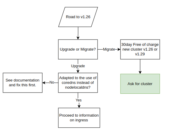
We have received, and acted upon, customer feedback since our main announcement 2023Q4. We provide two additional paths to reach v1.26:
- We’ve reverted to continue providing Ingress/Certmanager.
- To assist with your transition we can offer you an additional cluster (v1.26 or latest version) up to 30 days at no extra charge.
All customers will receive this information when we upgrade clusters to v1.26, which also includes the migration procedure. Make sure to carefully read through and understand the procedure and changes in order to avoid potential downtime during the upgrade.
Pre-Upgrade Information:
-
The following overall steps are crucial for a seamless upgrade process:
- Date for the upgrade is agreed upon.
- For users of Elastx managed ingress opting to continue with our management services:
- Elastx integrates a load balancer into the ingress service. The load balancer is assigned an external IP-address that will be used for all DNS records post-transition (do not point DNS to this IP at this point).
- Date of the traffic transition to the load balancer is agreed upon.
-
Important Note Before the Upgrade:
- Customers are required to carefully read and comprehend all changes outlined in the migration documentation to avoid potential downtime or disruptions.
- In case of any uncertainties or challenges completing the steps, please contact Elastx support. We are here to assist and can reschedule the upgrade to a more suitable date if needed.
To facilitate a seamless traffic transition, we recommend the following best practices:
- Utilize CNAMEs when configuring domain pointers for the ingress. This approach ensures that only one record needs updating, enhancing efficiency.
- Prior to implementing the change, verify that the CNAME record has a low Time-To-Live (TTL), with a duration of typically 1 minute, to promote rapid propagation.
During the traffic transition:
- All DNS records or proxies need to be updated to point towards the new loadbalancer
- In order to make this change as seamless as possible. We recommend the customer to make use of CNAMEs when pointing domains towards the ingress. This would ensure only one record needs to be updated. Prior to the change make sure the CNAME record has a low TTL, usually 1 minute is good to ensure rapid propagation
During the traffic transition:
- Elastx will meticulously update the ingress service configuration to align with your specific setup.
- The customer is responsible for updating all DNS records or proxies to effectively direct traffic towards the newly implemented load balancer.
During the Upgrade:
- Elastx assumes all necessary pre-upgrade changes have been implemented unless notified otherwise.
- On the scheduled upgrade day, Elastx initiates the upgrade process at the agreed-upon time.
- Note: The Kubernetes API will be temporarily unavailable during the upgrade due to migration to a load balancer.
- Upgrade Procedure:
- The upgrade involves replacing all nodes in your cluster twice.
- Migration to the new cluster management backend system will occur during Kubernetes 1.25, followed by the cluster upgrade to Kubernetes 1.26.
After Successful Upgrade:
- Users are advised to download a new kubeconfig from the object store for continued access and management.
Possibility to get a new cluster instead of migrating
To address the growing demand for new clusters rather than upgrades, customers currently running Kubernetes 1.25 (or earlier) can opt for a new Kubernetes cluster instead of migrating their existing one. The new cluster can be of version 1.26 or the latest available (1.29 at the moment). This new cluster is provided free of charge for an initial 30-day period, allowing you the flexibility to migrate your services at your own pace. However, if the migration extends beyond 30 days, please note that you will be billed for both clusters during the extended period. We understand the importance of a smooth transition, and our support team is available to assist you throughout the process.
Ingress
We are updating the way clusters accept incoming traffic by transitioning from accepting traffic on each worker node to utilizing a load balancer. This upgrade, effective from Kubernetes 1.26 onwards, offers automatic addition and removal of worker nodes, providing enhanced fault management and a single IP address for DNS and/or WAF configuration.
Before upgrading to Kubernetes 1.26, a migration to the new Load Balancer is necessary. See below a flowchart of the various configurations. In order to setup the components correctly we need to understand your configuration specifics. Please review your scenario:
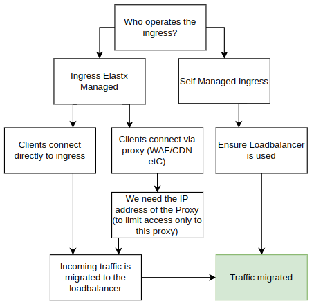
Using Your Own Ingress
If you manage your own add-ons, you can continue doing so. Starting from Kubernetes 1.26, clusters will no longer have public IP addresses on all nodes by default. We strongly recommend implementing a load balancer in front of your ingress for improved fault tolerance, especially in handling issues better than web browsers.
Elastx managed ingress
If you are using the Elastx managed ingress, additional details about your setup are required.
Proxy Deployed in Front of the Ingress (CDN, WAF, etc.)
If a proxy is deployed, provide information on the IP addresses used by your proxy. We rely on this information to trust the x-forwarded- headers. By default, connections that do not come from your proxy are blocked directly on the load balancer, enforcing clients to connect through your proxy.
Clients Connect Directly to Your Ingress
If clients connect directly to the ingress, we will redirect them to the new ingress. To maintain client source IPs, we utilize HAProxy proxy protocol in the load balancer. However, during the change, traffic will only be allowed to the load balancer for approximately 1-2 minutes. Please plan accordingly, as some connections may experience downtime during this transition.
Floating IPs
Floating IPs (FIPs) are now available for customers who choose to opt in. As part of the upgrade to Kubernetes 1.26, floating IPs will be removed from nodes by default. Instead, Load Balancers will be employed to efficiently direct traffic to services within the cluster.
Please note that current floating IPs will be lost if customers do not opt in for this feature during the upgrade process.
Should you wish to continue utilizing Floating IPs or enable them in the future, simply inform us, and we’ll ensure to assist you promptly.
A primary use case where Floating IPs prove invaluable is in retaining control over egress IP from the cluster. Without leveraging FIPs, egress traffic will be SNAT’ed via the hypervisor.
Kubernetes API
We are removing floating IPs for all control-plane nodes. Instead, we use a Load Balancer in front of control-planes to ensure the traffic will be sent to an working control-plane node.
Whitelisting of access to the API server is now controlled in the loadbalancer in front of the API. Currently, managing the IP-range whitelist requires a support ticket here. All Elastx IP ranges are always included.
Node local DNS
During the Kubernetes 1.26 upgrade we stop using the nodelocaldns. However to ensure we does not break any existing clusters the service will remain installed.
All nodes being added to the cluster running Kubernetes 1.26 or later will not make use of nodelocaldns and pods being created on upgraded nodes will instead make use of the CoreDNS service located in kube-system.
This may affect customers that make use of network policies. If the policy only allows traffic to nodelocaldns, it is required to update the policy to also allow traffic from the CoreDNS service.
Network policy to allow CoreDNS and NodeLocalDNS Cache
This example allows DNS traffic towards both NodeLocalDNS and CoreDNS. This policy is recommended for customers currently only allowing DNS traffic towards NodeLocalDNS and can be used in a “transition phase” prior to upgrading to Kubernetes 1.26.
apiVersion: networking.k8s.io/v1
kind: NetworkPolicy
metadata:
  name: allow-dns-access
spec:
  podSelector: {}
  egress:
    - ports:
        - protocol: UDP
          port: 53
        - protocol: TCP
          port: 53
      to:
        - ipBlock:
            cidr: 169.254.25.10/32
        - podSelector:
            matchLabels:
              k8s-app: kube-dns
  policyTypes:
    - Egress
Network policy to allow CoreDNS
This example shows an example network policy that allows DNS traffic to CoreDNS. This can be used after the upgrade to Kubernetes 1.26
apiVersion: networking.k8s.io/v1
kind: NetworkPolicy
metadata:
  name: allow-dns-access
spec:
  podSelector: {}
  egress:
    - ports:
        - protocol: UDP
          port: 53
        - protocol: TCP
          port: 53
      to:
        - podSelector:
            matchLabels:
              k8s-app: kube-dns
  policyTypes:
    - Egress
9 - Node labels and taints with elx-nodegroup-controller
The elx-nodegroup-controller lets you declaratively manage labels and taints
across groups of nodes in your cluster. Instead of manually patching each node
after it joins, you define a NodeGroup resource that describes which nodes to
target and what labels and taints to apply. The controller keeps the nodes
in sync automatically, even after node replacements due to auto-healing or
scaling.
The controller is available as a managed add-on through Elastx and can also be deployed from the public GitHub repository if you prefer to manage it yourself.
When is this useful?
A few common scenarios:
- GPU or specialised hardware nodes — taint dedicated nodes so only workloads that explicitly tolerate the taint are scheduled on them.
- Cost or zone affinity — label nodes by nodegroup so workloads can use
nodeAffinityto target specific node types. - Workload isolation — mark nodes reserved for databases, batch jobs, or frontend replicas using a combination of labels and taints.
Concepts
A NodeGroup resource targets nodes in two ways — you can use one or both in
the same resource:
| Field | Behaviour |
|---|---|
spec.members |
Explicit list of node names. Exact match. |
spec.nodeGroupNames |
List of name segments. A node matches if any dash-separated part of its name equals one of the listed segments. |
When a NodeGroup is deleted the controller removes only the labels and taints
it applied. Labels and taints that were on the node before the NodeGroup
existed are left untouched.
Applying labels to a nodegroup
The following example labels all nodes whose name contains the segment gpu
(e.g. worker-gpu-a, worker-gpu-b, sto1-gpu-1):
apiVersion: k8s.elx.cloud/v1alpha2
kind: NodeGroup
metadata:
  name: gpu-workers
spec:
  nodeGroupNames:
    - gpu
  labels:
    elastx.cloud/node-type: gpu
Apply it:
kubectl apply -f gpu-nodegroup.yaml
Verify the label was applied:
kubectl get nodes -l elastx.cloud/node-type=gpu
Adding a taint to restrict scheduling
Taints prevent workloads from being scheduled on a node unless they explicitly
tolerate the taint. This example taints the same gpu nodes with NoSchedule
so that only GPU-aware workloads land on them:
apiVersion: k8s.elx.cloud/v1alpha2
kind: NodeGroup
metadata:
  name: gpu-workers
spec:
  nodeGroupNames:
    - gpu
  labels:
    elastx.cloud/node-type: gpu
  taints:
    - key: elastx.cloud/gpu
      value: "true"
      effect: NoSchedule
A pod that should run on these nodes needs a matching toleration:
tolerations:
  - key: elastx.cloud/gpu
    operator: Equal
    value: "true"
    effect: NoSchedule
Targeting nodes by name
If you want to target specific nodes rather than relying on naming patterns,
list them explicitly in spec.members:
apiVersion: k8s.elx.cloud/v1alpha2
kind: NodeGroup
metadata:
  name: database-nodes
spec:
  members:
    - worker-sto1-db-1
    - worker-sto2-db-1
    - worker-sto3-db-1
  taints:
    - key: elastx.cloud/role
      value: database
      effect: NoSchedule
  labels:
    elastx.cloud/role: database
You can mix members and nodeGroupNames in the same resource — the sets are
merged and deduplicated automatically.
Good to know
- Reserved label prefixes — the controller will reject a
NodeGroupthat tries to set labels with the prefixeskubernetes.io/,k8s.io/,node.kubernetes.io/, ornode-role.kubernetes.io/. These are reserved for Kubernetes itself. - Taint effects — valid values are
NoSchedule,PreferNoSchedule, andNoExecute. - Limits — a single
NodeGroupsupports up to 500 explicit members, 50 name segments, 64 labels, and 100 taints. - Cleanup on delete — deleting a
NodeGrouptriggers the controller to remove the labels and taints it applied before the resource is fully removed. The controller uses a finalizer to ensure this happens even if the deletion races with a node replacement. - Node replacements — when auto-healing replaces a node the new node will receive the correct labels and taints on its first reconciliation, no manual intervention needed.
10 - Persistent volumes
Persistent volumes in our Elastx Kubernetes CaaS service are provided by OpenStack Cinder. Volumes are dynamically provisioned by Kubernetes Cloud Provider OpenStack.
Storage classes
8k refers to 8000 IOPS.
See our pricing page under the table Storage to calculate your costs.
Below is the list of storage classes provided in newly created clusters. In case you see other storageclasses in your cluster, consider these legacy and please migrate data away from them. We provide a guide to Change PV StorageClass.
$ kubectl get storageclasses
NAME              PROVISIONER                RECLAIMPOLICY   VOLUMEBINDINGMODE      ALLOWVOLUMEEXPANSION   AGE
v2-128k           cinder.csi.openstack.org   Delete          WaitForFirstConsumer   true                   27d
v2-16k            cinder.csi.openstack.org   Delete          WaitForFirstConsumer   true                   27d
v2-1k (default)   cinder.csi.openstack.org   Delete          WaitForFirstConsumer   true                   27d
v2-32k            cinder.csi.openstack.org   Delete          WaitForFirstConsumer   true                   27d
v2-4k             cinder.csi.openstack.org   Delete          WaitForFirstConsumer   true                   27d
v2-64k            cinder.csi.openstack.org   Delete          WaitForFirstConsumer   true                   27d
v2-8k             cinder.csi.openstack.org   Delete          WaitForFirstConsumer   true                   27d
Example of PersistentVolumeClaim
A quick example of how to create an unused 1Gi persistent volume claim named example:
kind: PersistentVolumeClaim
apiVersion: v1
metadata:
  name: example
spec:
  accessModes:
    - ReadWriteOnce
  volumeMode: Filesystem
  resources:
    requests:
      storage: 1Gi
  storageClassName: v2-16k
$ kubectl get persistentvolumeclaim
NAME      STATUS   VOLUME                                     CAPACITY   ACCESS MODES   STORAGECLASS   AGE
example   Bound    pvc-f8b1dc7f-db84-11e8-bda5-fa163e3803b4   1Gi        RWO            v2-16k            18s
Good to know
Cross mounting of volumes between nodes
Cross mounting of volumes is not supported! That is a volume can only be mounted by a node residing in the same availability zone as the volume. Plan accordingly for ensured high availability!
Limit of volumes and pods per node
In case higher number of volumes or pods are required, consider adding additional worker nodes.
| Kubernetes version | Max pods/node | Max volumes/node |
|---|---|---|
| v1.25 and lower | 110 | 25 |
| v1.26 and higher | 110 | 125 |
Encryption
All volumes are encrypted at rest in hardware.
Volume type hostPath
A volume of type hostPath is in reality just a local directory on the specific node being mounted in a pod, this means data is stored locally and will be unavailable if the pod is ever rescheduled on another node. This is expected during cluster upgrades or maintenance, however it may also occur because of other reasons, for example if a pod crashes or a node is malfunctioning. Malfunctioning nodes are automatically healed, meaning they are automatically replaced.
You can read more about hostpath here.
If you are looking for a way to store persistent data we recommend to use PVCs. PVCs can move between nodes within one data-center meaning any data stored will be present even if the pod or node is recreated.
Known issues
Resizing encrypted volumes
Legacy: encrypted volumes do not resize properly, please contact our support if you wish to resize such a volume.
11 - Your first deployment
This page will help you getting a deployment up and running and exposed as a load balancer.
Note: This guide is optional and only here to help new Kubernetes users with an example deployment.
You can verify access by running kubectl get nodes and if the output is similar to the example below you are set to go.
❯ kubectl get nodes
NAME                           STATUS   ROLES           AGE     VERSION
hux-lab1-control-plane-c9bmm   Ready    control-plane   2d18h   v1.27.3
hux-lab1-control-plane-j5p42   Ready    control-plane   2d18h   v1.27.3
hux-lab1-control-plane-wlwr8   Ready    control-plane   2d18h   v1.27.3
hux-lab1-worker-447sn          Ready    <none>          2d18h   v1.27.3
hux-lab1-worker-9ltbp          Ready    <none>          2d18h   v1.27.3
hux-lab1-worker-htfbp          Ready    <none>          15h     v1.27.3
hux-lab1-worker-k56hn          Ready    <none>          16h     v1.27.3
Creating an example deployment
To get started we need a deployment to deploy.
Below we have a deployment called echoserver we can use for this example.
-
Start off by creating a file called
deployment.yamlwith the content of the deployment below:--- apiVersion: apps/v1 kind: Deployment metadata: labels: app.kubernetes.io/name: echoserver name: echoserver spec: replicas: 3 selector: matchLabels: app.kubernetes.io/name: echoserver template: metadata: labels: app.kubernetes.io/name: echoserver spec: containers: - image: gcr.io/google-containers/echoserver:1.10 name: echoserver -
After you have created your file we can apply the deployment by running the following command:
❯ kubectl apply -f deployment.yaml deployment.apps/echoserver created -
After running the apply command we can verify that 3 pods have been created. This can take a few seconds.
❯ kubectl get pod
NAME                          READY   STATUS    RESTARTS   AGE
echoserver-545465d8dc-4bqqn   1/1     Running   0          51s
echoserver-545465d8dc-g5xxr   1/1     Running   0          51s
echoserver-545465d8dc-ghrj6   1/1     Running   0          51s
Exposing our deployment
After your pods are created we need to make sure to expose our deployment. In this example we are creating a service of type loadbalancer. If you run this application in production you would likely install an ingress controller
-
First of we create a file called
service.yamlwith the content of the service below--- apiVersion: v1 kind: Service metadata: labels: app.kubernetes.io/name: echoserver name: echoserver annotations: loadbalancer.openstack.org/x-forwarded-for: "true" spec: ports: - port: 80 protocol: TCP targetPort: 8080 name: http selector: app.kubernetes.io/name: echoserver type: LoadBalancer -
After creating the service.yaml file we apply it using kubectl
❯ kubectl apply -f service.yaml service/echoserver created -
We should now be able to use our service by running
kubectl get service❯ kubectl get service NAME TYPE CLUSTER-IP EXTERNAL-IP PORT(S) AGE echoserver LoadBalancer 10.98.121.166 <pending> 80:31701/TCP 54s kubernetes ClusterIP 10.96.0.1 <none> 443/TCP 2d20hFor the echo service we can see that
EXTERNAL-IPsays<pending>this means that a load balancer is being created but is not yet ready. As soon as the load balancer is up and running we will instead use an IP address here we can use to access our application.Loadbalancers usually take around a minute to be created however can sometimes take a little longer.
-
Once the load balancer is up and running the
kubectl get serviceshould return something like this:❯ kubectl get service NAME TYPE CLUSTER-IP EXTERNAL-IP PORT(S) AGE echoserver LoadBalancer 10.98.121.166 185.24.134.39 80:31701/TCP 2m24s kubernetes ClusterIP 10.96.0.1 <none> 443/TCP 2d20h
Access the example deployment
Now if we open our web browser and visits the IP address we should get a response looking something like this:
Hostname: echoserver-545465d8dc-ghrj6

Pod Information:
  -no pod information available-

Server values:
  server_version=nginx: 1.13.3 - lua: 10008

Request Information:
  client_address=192.168.252.64
  method=GET
  real path=/
  query=
  request_version=1.1
  request_scheme=http
  request_uri=http://185.24.134.39:8080/

Request Headers:
  accept=text/html,application/xhtml+xml,application/xml;q=0.9,image/avif,image/webp,image/apng,*/*;q=0.8,application/signed-exchange;v=b3;q=0.7
  accept-encoding=gzip, deflate
  accept-language=en-US,en;q=0.9,sv;q=0.8
  host=185.24.134.39
  upgrade-insecure-requests=1
  user-agent=Mozilla/5.0 (X11; Linux x86_64) AppleWebKit/537.36 (KHTML, like Gecko) Chrome/114.0.0.0 Safari/537.36
  x-forwarded-for=90.230.66.18

Request Body:
  -no body in request-
The Hostname shows which pod we reached and if we refresh the page we should be able to see this value change.
Cleanup
To clean up everything we created you an run the following set of commands
-
We can start off by removing the deployment. To remove a deployment we can use kubectl delete and point it towards the file containing our deployment:
❯ kubectl delete -f deployment.yaml deployment.apps "echoserver" deleted -
After our deployment are removed we can go ahead and remove our service and load balancer. Please note that this takes a few seconds since we are waiting for the load balancer to be removed.
❯ kubectl delete -f service.yaml
service "echoserver" deleted